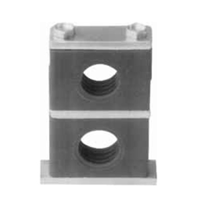
Plastic pipe clamp JB / zq4008-97
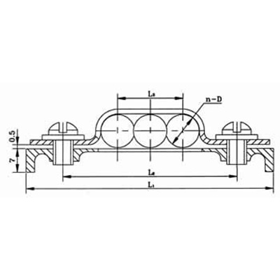
适用于以油、水、气为介质的管道固定用塑料管夹。工作温度为-5~+100℃。 A 系列管夹适用于中压、低压(PN≤8MPa)管道的固定;B系列管夹及B系列Ⅰ型组合安装管夹适用于中高压、高压(PN≤31.5MPa)管道的固定。
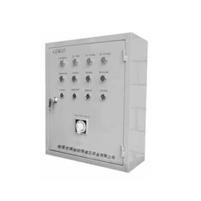
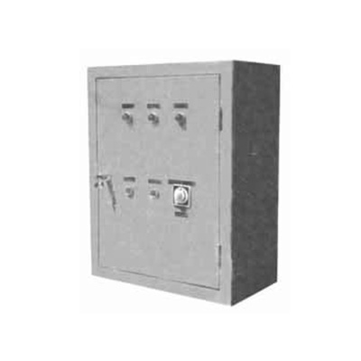
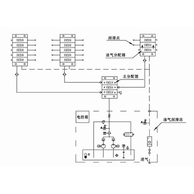
Gdko3 type electric control box has two types: monitoring and full-automatic. It is applicable to the 40MPa double line terminal dry oil centralized lubrication system. It is used to control the coordinated work of the lubrication pump, reversing valve, grease replenishing pump, etc. it can automatically supply oil to the oil supply points in the system. After the oil supply is completed, it will automatically stop. When the liquid level in the oil tank is lower than a certain limit, the grease replenishing pump will start automatically and stop automatically after filling with oil.
Key Word:
Electric control box | tyre repair pump | hydraulic equipment
Category:
Pipe fittings
Product Description
1、 Overview
Gdko3 type electric control box has two types: monitoring and full-automatic. It is applicable to the 40MPa double line terminal dry oil centralized lubrication system. It is used to control the coordinated work of the lubrication pump, reversing valve, grease replenishing pump, etc. it can automatically supply oil to the oil supply points in the system. After the oil supply is completed, it will automatically stop. When the liquid level in the oil tank is lower than a certain limit, the grease replenishing pump will start automatically and stop automatically after filling with oil.
This control box can send out fault signals such as "extended oil supply time", "empty oil reservoir", "overload operation", etc. It has continuous, manual and automatic control working states, which can be switched through the change-over switch on the box surface. Continuous working state: when the lubricating pump is started, it continuously supplies lubricating grease to the two main lines of the system; Manual working state: when the interlocking signal with the main engine is connected, the lubricating pump is manually started to feed the lubricating grease to the steering system, and the automatic reversing is automatically stopped after one lubrication cycle is completed; Automatic working state: when the interlocking signal with the main engine is connected, the lubricating pump will supply lubricating grease to the system at regular intervals according to the time interval set by the system, and it will automatically stop after completing a lubrication cycle. No matter what state the lubricating pump is in, once the oil reservoir is empty, the grease replenishing pump will automatically start to replenish grease and stop automatically after replenishing.
2、 Overall dimensions
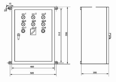
3、 Sign symbols and words
| Serial number |
Symbol
|
Nameplate text
|
Serial number
|
Symbol
|
Nameplate text
|
Serial number
|
Symbol
|
Nameplate text
|
|
1
|
HL1
|
Work preparation instructions
|
6
|
HL6
|
System overpressure
|
11
|
SB4
|
Refueling pump start
|
|
2
|
HL2
|
Working state of line I
|
7
|
HL7
|
Pump motor overload
|
12
|
SB5
|
Refueling pump stop
|
|
3
|
HL3
|
Working state of line II
|
8
|
HL8
|
Oil reservoir empty
|
13
|
SB3
|
Fault reset
|
|
4
|
HL4
|
Refueling pump operation
|
9
|
SB1
|
Lubrication pump start
|
14
|
SA1
|
Automatic / manual / continuous
|
|
5
|
HL5
|
Monitoring time exceeds
|
10
|
SB2
|
Lubrication pump stop
|
15
|
SA2
|
Off / bell / on
|
一、概述
|
适用于以油、水、气为介质的管道固定用塑料管夹。工作温度为-5~+100℃。
|
二、外形尺寸 1.1 A系列管夹的型式和尺寸见图1和表1。
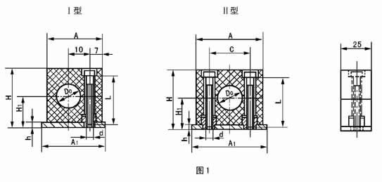
表1
|
型式
|
管子
外径 Do |
A
|
A1
|
C
|
H
|
H1
|
h
|
螺栓
|
重量
kg≈ |
型式
|
管子
外径 Do |
A
|
A1
|
C
|
H
|
H1
|
h
|
螺栓
|
重量
kg≈ |
||
|
d
|
L
|
d
|
L
|
||||||||||||||||||
|
I
|
6
|
28
|
33
|
-
|
32
|
19
|
6
|
M6
|
20
|
0.06
|
II
|
20
|
48
|
53
|
33
|
42
|
24
|
6
|
M6
|
30
|
0.14
|
|
8
|
22
|
||||||||||||||||||||
|
10
|
25
|
||||||||||||||||||||
|
12
|
28
|
70
|
75
|
52
|
64
|
35
|
50
|
0.19
|
|||||||||||||
|
II
|
6
|
34
|
39
|
20
|
0.08
|
30
|
|||||||||||||||
|
8
|
32
|
||||||||||||||||||||
|
10
|
34
|
||||||||||||||||||||
|
12
|
40
|
||||||||||||||||||||
|
14
|
40
|
45
|
26
|
40
|
23
|
25
|
0.12
|
42
|
|||||||||||||
|
16
|
48
|
86
|
91
|
66
|
72
|
39
|
60
|
0.22
|
|||||||||||||
|
18
|
50
|
||||||||||||||||||||
| 注:静压油腊润滑管路,压力至10MPa,仍可选用A系列管夹。 | |||||||||||||||||||||
1.2 B 型管夹的型式和尺寸见图2 和表2
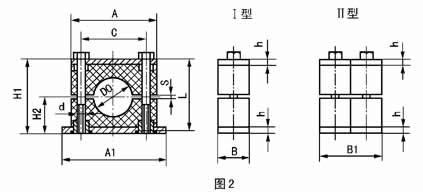
表2
|
型式
|
管子
外径 Do |
A
|
A1
|
B
|
B1
|
C
|
H1
|
H2
|
h
|
s
|
螺纹
|
重量 kg≈
|
||
|
d
|
L
|
I型
|
II型
|
|||||||||||
|
I、
II |
10、12
|
55
|
73
|
30
|
60
|
33
|
48
|
24
|
8
|
2
|
M10
|
45
|
0.3
|
0.6
|
|
14、16
|
||||||||||||||
|
18、20、22
|
70
|
85
|
45
|
64
|
32
|
60
|
0.4
|
0.8
|
||||||
|
25、28
|
||||||||||||||
|
30、32、34
|
84
|
100
|
60
|
76
|
38
|
70
|
0.5
|
1.0
|
||||||
|
40、42
|
||||||||||||||
|
48、50、57
|
115
|
150
|
45
|
90
|
90
|
110
|
55
|
10
|
3
|
M12
|
100
|
1.8
|
3.6
|
|
|
60、63.5
|
||||||||||||||
|
76、89
|
152
|
200
|
60
|
120
|
122
|
140
|
70
|
3.5
|
M16
|
130
|
2.5
|
5.0
|
||
|
102、108
|
205
|
270
|
80
|
160
|
168
|
200
|
100
|
15
|
4.5
|
M20
|
190
|
5.5
|
11
|
|
|
114、127
|
||||||||||||||
|
138、140
|
250
|
310
|
90
|
180
|
205
|
230
|
115
|
M24
|
220
|
8
|
16
|
|||
|
159、168
|
||||||||||||||
| 注:当管路介质压力较高时,可选用B系列I型和II型,但需缩小相邻管夹间距。 | ||||||||||||||
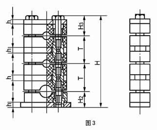
1.2.1 B 型系列Ⅰ型组合安装夹的型式和尺寸见图3 和表3。
a)同一外形尺寸的B 型系列Ⅰ型管夹,可叠垒成组成安装,但最多不超过5 根管子。
|
管子外径
Do |
10
|
12
|
14
|
16
|
18
|
20
|
22
|
25
|
28
|
32
|
34
|
40
|
42
|
48
|
50
|
57
|
60
|
63.5
|
76
|
89
|
102
|
108
|
114
|
127
|
133
|
140
|
159
|
168
|
|
H3
|
31
|
39
|
45
|
63
|
80
|
113
|
130
|
|||||||||||||||||||||
|
T
|
40
|
56
|
68
|
100
|
130
|
185
|
215
|
|||||||||||||||||||||
b)尺寸计算 H=H2+H3+(N-1)·T
式中:N ——管子根数:
T ——相邻管距(见表3),mm;
H2、H3见表2和表3
◎注:组合安装管夹的每组重量可近似按(N-0.5)乘以表2中的单件重量。
2.1 标记说明
A 系列Ⅰ型、管子外径为12mm的塑料管夹:
塑料管夹A(Ⅰ)12 JB/ZQ4008-97
B 系列Ⅱ型、管子外径为28mm 的塑料管夹;
塑料管夹B(Ⅱ)28 JB/ZQ4008-97
B 系列Ⅰ型组合叠装、管子外径为22mm的3根、管子外径为28mm的2根的塑料管夹;
塑料管夹B(Ⅰ)22×3-28×2JB/ZQ4008-97
三、管夹承载能力
(A1,A2 及图A1,图A2)
A1 表示方法:管夹承受管子轴向力的能力大小,用曲线图表示。
A2 具体内容:图A1 用于“A 系列管夹”;图A2 用于“B 系列Ⅰ型管夹”。a 曲线表示管夹与管子处于“静摩擦状态”时,管子外径尺寸与管夹承受管子轴向力的函数关系。b曲线表示管夹与管子处于“动摩擦状态”时,管子外径尺寸与管夹承受管子轴向力及转矩的函数关系。

|
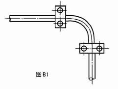
四、安装说明(B1~B3)
|
RELATED PRODUCTS
CONSULTING PRODUCTS


